bypass diode
The destructive effects of hot-spot heating may be circumvented through the use of a bypass diode. A diode is connected in parallel, but with opposite polarity, to a solar cell as shown below. Under normal operation, each solar cell will be forward biased and therefore the bypass diode will be reverse biased and will effectively be an open circuit. However, if a solar cell is reverse biased due to a mismatch in short-circuit current between several series connected cells, then the bypass diode conducts, thereby allowing the current from the good solar cells to flow in the external circuit rather than forward biasing each good cell. The maximum reverse bias across the poor cell is reduced to about a single diode drop, thus limiting the current and preventing hot-spot heating. The operation of a bypass diode and the effect on an IV curve are shown in the animation below.
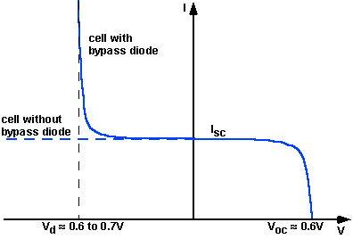
The effect of a diode on an IV curve can be determined by first finding the IV curve of a single solar cell with a bypass diode and then combining this curve with other solar cell IV curves. The bypass diode affects the solar cell only in reverse bias. If the reverse bias is greater than the knee voltage of the solar cell, then the diode turns on and conducts current. The combined IV curve is shown in the figure below.
IV curve of solar cell with bypass diode.
Preventing hot-spot heating with a bypass diode. For clarity, the example uses a total of 10 cells with 9 unshaded and 1 shaded. A typical module contains 36 cells and the effects of current mismatch are even worse without the bypass diode, but are less important with the bypass diode.
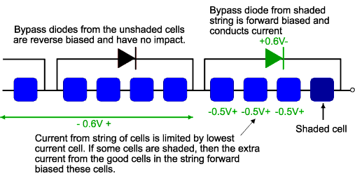
In practice, however, one diode per solar cell is generally too expensive and instead bypass diodes are usually placed across groups of solar cells. The voltage across the shaded or low current solar cell is equal to the forward bias voltage of the other series cells which share the same bypass diode plus the voltage of the bypass diode. This is shown in the figure below. The voltage across the unshaded solar cells depends on the degree of shading on the low current cell. For example, if the cell is completely shaded, then the unshaded solar cells will be forward biased by their short circuit current and the voltage will be about 0.6V. If the poor cell is only partially shaded, the some of the current from the good cells can flow through the circuit, and the remainder is used to forward bias each solar cell junction, causing a lower forward bias voltage across each cell. The maximum power dissipation in the shaded cell is approximately equal to the generating capability of all cells in the group. The maximum group size per diode, without causing damage, is about 15 cells/bypass diode, for silicon cells. For a normal 36 cell module, therefore, 2 bypass diodes are used to ensure the module will not be vulnerable to “hot-spot” damage.

Diodes across groups of solar cells. The voltage across the unshaded solar cells depends on the degree of shading of the poor cell. In the figure above, 0.5V is arbitrarily shown.
